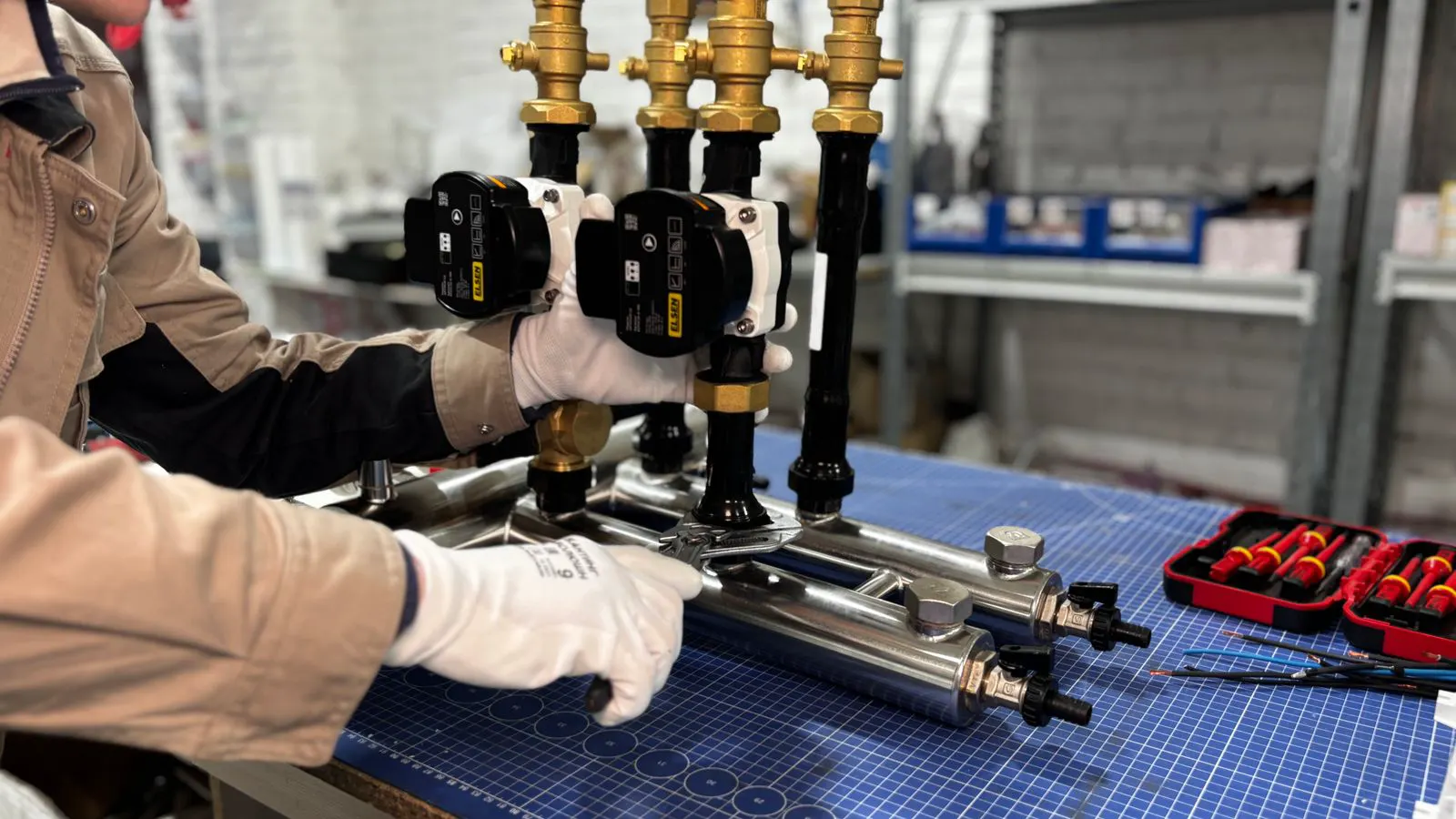
Hollow Shaft vs Cylindrical Speed Reducer Comparison
A hollow shaft speed reducer uses a through-bore for direct coupling alignment, while a cylindrical shaft unit uses side-mounted couplings or belts. The choice depends on installation space, shaft access, and how the load connects to the driven equipment.
- Hollow shaft reducers keep the input and output axes in a straight line, which simplifies coupling alignment.
- Cylindrical shaft reducers place the shaft end on the side of the housing, which can save space but requires offset couplings.
- Hollow shaft designs often allow access to bearings and seals without removing the motor from the line.
- Cylindrical shaft designs are easier to inspect for shaft keyways and coupling hardware from the outside.
- Selection should match the available mounting position, the type of driven load, and the maintenance access path.
What structural difference changes the layout
The main difference between a hollow shaft speed reducer and a cylindrical shaft speed reducer is where the output power exits the housing. A hollow shaft unit provides a through-bore along the centerline. The shaft passes through the housing, and the output coupling sits on the same axis as the input shaft or motor coupling. A cylindrical shaft unit provides a short protruding shaft on the side of the housing. The output coupling, belt, chain, or gear attaches to that side shaft.
This difference affects alignment, mounting, and maintenance. A through-bore design works well when the motor and driven load sit on the same line. A side-shaft design works well when the driven load is offset, or when the mounting position is constrained by the machine frame. The speed reducer selection decision starts with the physical path of the power train, not with the torque rating alone.
How alignment works in each design
Hollow shaft reducers are simpler to align because the input and output are coaxial. The motor coupling and the driven coupling sit on the same centerline. A straight-line alignment check can be done with a dial indicator, a laser alignment tool, or a straightedge across the couplings. The housing does not need to move sideways to compensate for shaft offset.
Cylindrical shaft reducers change the alignment task. The output shaft is offset from the input axis. The coupling must bridge the distance between the motor shaft and the side shaft. This can require a flexible coupling, an offset flange, a belt, or a chain. The alignment tolerances are usually tighter on the output side because the bearing load is transmitted through the housing wall and the side bearing.
A common mistake is to assume that any speed reducer can be dropped into an existing frame without checking the shaft centerline. If the driven equipment expects a straight-line input, a cylindrical shaft unit may force an extra coupling or a custom adapter plate. If the frame only allows a side mount, a hollow shaft unit may not fit unless the motor is moved.
Installation space and mounting constraints
Hollow shaft reducers are longer along the axis. The through-bore adds length, and the input coupling often needs clearance on both ends of the housing. The mounting footprint is usually a simple end-mounted frame or a base plate. The motor can sit directly in line with the reducer. This makes the unit easy to install in conveyor lines, pump drives, and fan drives where the equipment is laid out in a straight row.
Cylindrical shaft reducers are shorter in the axial direction. The side shaft exits through the housing wall, which can reduce the total length required in the line. The mounting may be more flexible because the side shaft can point in different directions. Some reducers are mounted with the side shaft up, down, left, or right. This can fit into frames where a straight line is not possible.
The trade-off is coupling access. A side shaft may sit close to the machine frame, the gearbox housing, or other components. The coupling and bearing protection need clearance. A hollow shaft may be easier to service because the input and output couplings are on the same line and can be accessed from either end.
Maintenance and service access
A hollow shaft design often allows the motor and reducer to be separated without disturbing the driven load. The output coupling can be removed from the through-bore, and the motor can be slid out. This is useful when the motor needs replacement or when the reducer bearings need cleaning. The through-bore also allows a bearing puller or seal tool to approach the output bearing from the side.
A cylindrical shaft design can make service more difficult if the side shaft is in a tight space. The coupling may need to be removed before the reducer can be rotated or lifted. The side bearing is often located in a boss or cap that may require removal to reach the shaft. If the side shaft is short, the coupling may interfere with the housing during disassembly.
Both designs need lubrication checks, seal inspection, and alignment verification after major maintenance. The hollow shaft may have easier access to the input and output bearings if the housing is split. The cylindrical shaft may have easier access to the side bearing if it is a cap-mounted type. The service access should match the maintenance crew, the tools available, and the downtime window.
Comparison of hollow shaft and cylindrical shaft speed reducer designs
| Option | Best for | Limitations |
|---|---|---|
| Hollow shaft | Straight-line coupling, direct motor connection, through-bore access | Adds axial length, requires alignment on the same centerline, may need longer coupling clearance |
| Cylindrical shaft | Offset mounting, side-mounted driven equipment, compact axial footprint | Requires offset coupling or belt, side bearing access can be restricted, alignment is more complex |
| Hollow shaft with flange | Flange-mounted motors, direct drive applications | Flange and through-bore alignment must be checked, longer overall length |
| Cylindrical shaft with belt or chain | Long offset distances, flexible alignment, high-speed applications | Adds belt or chain maintenance, lower efficiency than direct coupling, guard requirements |
| Hollow shaft with adapter | Existing equipment where motor must stay in line but reducer size differs | Adapter adds cost and alignment tolerance, may reduce service access |
When to pick a hollow shaft reducer
A hollow shaft speed reducer is a good choice when the motor, reducer, and driven load sit on the same line. The through-bore keeps the power train straight, which reduces coupling stress and simplifies alignment. It is a common choice for conveyor drives, pump drives, fan drives, and any application where the driven equipment expects a coaxial input.
The hollow shaft design is also useful when the motor may need to be removed for service. The through-bore allows the motor to be slid out without moving the driven load. It can be easier to inspect the output bearing because the shaft end is open on the through-bore side. The alignment check is simpler because the centerline is the same as the input.
The main limitation is length. The through-bore adds axial space, and the coupling may need clearance on both ends. If the machine frame is tight in the axial direction, the hollow shaft may not fit. In that case, a cylindrical shaft design or a flange-mounted unit may be a better fit.
When to pick a cylindrical shaft reducer
A cylindrical shaft speed reducer is a good choice when the driven load is offset from the motor. The side shaft can point up, down, left, or right, which can fit into a frame where a straight line is not possible. It is often used when the motor and reducer must share a compact mounting area, or when the driven equipment is mounted to the side of the machine.
The side shaft allows a coupling, belt, or chain to connect to the driven load. A flexible coupling can absorb some misalignment. A belt or chain can cover a longer distance and provide easier access for adjustment. This can be useful when the driven load moves, or when the alignment is difficult to hold tight during assembly.
The main limitation is the offset. The side bearing must carry the load from the shaft into the housing. The coupling may be closer to the machine frame, which can limit access. The alignment task is more complex because the input and output axes are not the same. The coupling must be checked for both parallelism and angular misalignment.
How to verify the selection before ordering
The speed reducer selection should be verified against the machine drawing, the motor coupling, and the driven load. The first check is the centerline. If the motor and driven load are on the same axis, a hollow shaft design is usually the simpler match. If the driven load is offset, a cylindrical shaft design may fit better.
The second check is coupling clearance. A hollow shaft may need space for the coupling on the through-bore side. A cylindrical shaft may need space for the side coupling and the side bearing cap. Measure the available depth, width, and height at the mounting position. Add room for the coupling, the guard, and the service tool.
The third check is service access. Can the coupling be removed without moving the driven load? Can the motor be removed without disturbing the reducer? Can the bearing be inspected without removing the housing? If the answer is no, the design may cause downtime that is not worth the space saving.
The final check is alignment tolerance. A hollow shaft design usually tolerates a simpler alignment check. A cylindrical shaft design may need a flexible coupling or a belt to absorb the offset. The coupling type should match the misalignment tolerance of the shaft and the speed of the drive. The selection document should state the shaft type, the coupling type, and the alignment method used.
Common sizing mistakes to avoid
A common mistake is to choose the shaft type based on catalog appearance instead of the machine layout. The reducer may be available in both hollow shaft and cylindrical shaft versions, but the housing dimensions, coupling clearance, and mounting bolt pattern can differ. The catalog page should be checked against the actual machine frame.
Another mistake is to ignore the coupling length. A hollow shaft through-bore may require a longer coupling than expected. A cylindrical shaft side coupling may sit close to the housing and limit the coupling length. The coupling manufacturer should be involved early, because the coupling dimensions affect the reducer selection.
A third mistake is to assume that the same torque rating works the same way in both designs. The torque is transmitted through the shaft and the housing. A hollow shaft may have a larger diameter at the through-bore. A cylindrical shaft may have a smaller diameter at the side shaft. The shaft strength and the bearing load should be checked against the duty cycle, not just the nameplate torque.
The selection should be confirmed in a sizing checklist that lists the shaft type, the coupling type, the alignment method, the service access path, and the duty cycle. This checklist should be reviewed by the engineer, the buyer, and the maintenance team before the order is placed.
Frequently asked questions
Can a hollow shaft speed reducer be used with a belt or chain drive?
Yes, if a coupling or pulley is mounted on the through-bore shaft end. The belt or chain then attaches to that end. The main difference is that the drive path is still on the centerline, so the alignment is simpler than a side-shaft offset.
Is a cylindrical shaft speed reducer always shorter than a hollow shaft unit?
Not always. The cylindrical shaft unit is usually shorter in the axial direction, but the side shaft and coupling may add width. The overall footprint depends on the mounting position and the coupling type. Measure the frame before deciding.
Which design is easier to service when the motor must be removed?
A hollow shaft design is usually easier because the motor can slide out along the through-bore without moving the driven load. A cylindrical shaft design may require removing the side coupling first, which can take extra time if the space is tight.
Can a cylindrical shaft reducer be aligned to a straight-line motor?
It can, but it usually requires an offset coupling, a flange adapter, or a custom mounting plate. The alignment is more complex than a hollow shaft design because the output axis is offset from the input axis.
How does the shaft type affect the speed reducer selection for continuous loads?
The shaft type does not change the torque rating by itself, but it changes the coupling load and the alignment stress. For continuous loads, the coupling and the shaft should match the duty cycle. A hollow shaft may be simpler to keep aligned over time, while a cylindrical shaft may need a flexible coupling to absorb offset loads.