Checklist: Verifying Gearbox Thermal Ratings for Duty Cycles
Engineers must match the reducer thermal rating to actual heat generation. This audit checklist provides a step by step method to verify heat dissipation capacity and duty cycle limits before installation.
- Match heat generation to heat removal using the specific duty cycle profile.
- Check nameplate derating values for ambient temperature and enclosure conditions.
- Verify oil level, filter state, and cooling fan status during commissioning.
- Monitor housing surface temperature at steady state to validate calculations.
- Red flags include persistent warm spots, frequent oil changes, and alarm trips.
Why Thermal Ratings Matter for Duty Cycles
A gearbox thermal rating describes the maximum continuous heat the drive can shed without exceeding safe internal temperatures. This limit depends on gear material, housing geometry, lube volume, and ambient conditions. Most selection errors occur when engineers assume a nameplate rating applies to any operating profile. The nameplate often reflects a continuous 100 percent load at a standard ambient temperature, such as 40 degrees Celsius. Your application may run at 80 percent load for ten minutes and then idle. The thermal mass of the gears and housing absorbs this heat during the run phase. If the idle phase is too short, the temperature keeps rising cycle after cycle. The result is thermal degradation, not mechanical wear.
Defining the Actual Heat Load
Start by calculating the power loss during the operating cycle. The primary heat source is friction in the gears and bearings. Secondary heat comes from the motor and drive electronics if they sit inside the same enclosure. Use the motor efficiency curve to find the electrical power consumed at the specific speed and torque. The difference between electrical input and mechanical output is heat.
For a variable speed application, do not average the power. The thermal response of the housing is slow. A short high power burst can push the oil temperature up, and the housing may not cool down before the next burst.
Checklist: Heat Load Calculation
- Record the exact speed and torque for every operating segment.
- Determine the motor efficiency at each point on the curve.
- Calculate the electrical input power for each segment.
- Subtract the mechanical output power to find the heat generation rate.
- Weight each heat rate by its duration within one full cycle.
- Identify the peak heat rate, not just the average.
Verifying the Nameplate Thermal Rating
The nameplate thermal rating, often expressed as a torque limit at a specific ambient temperature, is a static value. It does not tell you how the drive behaves under intermittent loads. You must cross reference this value against your calculated heat load.
Many manufacturers provide a thermal derating chart. This chart shows how the allowable torque drops as ambient temperature rises. If your installation is in a hot plant or a poorly ventilated skid, apply the derating factor. A reducer rated for 50 percent duty at 40 degrees Celsius may only handle 40 percent at 50 degrees.
Red Flags
- The nameplate lists a torque rating but no ambient temperature condition.
- The manufacturer does not provide a derating chart for high ambient temperatures.
- The rating assumes an open housing when your application uses a closed or enclosed skid.
Heat Dissipation Capacity of the Housing
The housing acts as a heat sink. Its surface area and material determine how fast it sheds heat to the air. Cast iron housings have high thermal mass but low surface area per unit volume. They take time to heat up but also take time to cool. Aluminum housings have lower mass and higher surface area, allowing faster heat rejection.
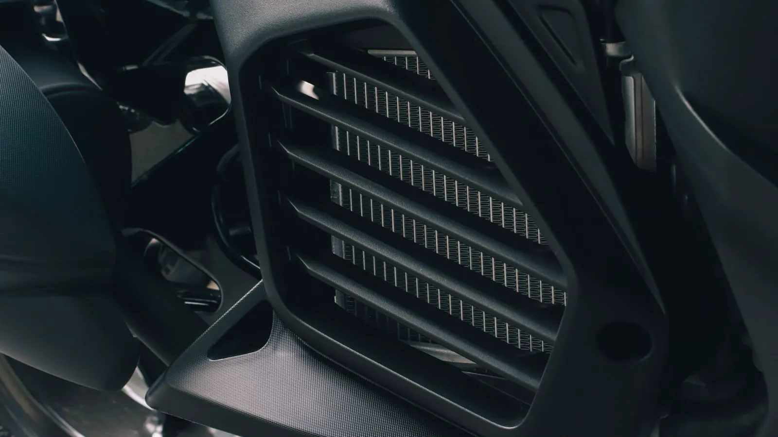
Check the cooling method specified in the datasheet. Some drives rely on passive air cooling. Others use a cooling fan or a liquid chiller. If the datasheet specifies a fan, verify that the fan is installed and unobstructed. A fan blocked by a guard or a nearby wall can cut heat dissipation in half.
| Cooling Method | Typical Application | Key Check Point |
|---|---|---|
| Passive Air | Low heat loads, ambient below 40C | Surface area, paint color, airflow |
| Forced Air Fan | Medium heat loads, enclosed skids | Fan RPM, filter state, obstruction |
| Liquid Chiller | High heat loads, hot environments | Pump flow rate, coolant volume |
| Oil Flow | Continuous high torque, heavy duty | Filter pressure drop, oil level |
Lubricant Selection and Maintenance Impact
The thermal rating of a gearbox is closely tied to the lubricant. The viscosity of the oil affects heat transfer inside the gear mesh. A thinner oil may cool the gears faster but might not provide enough film strength under high torque. A thicker oil holds a better film but dissipates heat more slowly.
The viscosity grade must match the ambient temperature and the gear speed. If you use a standard mineral oil in a hot environment, the viscosity may drop to a level where the film breaks down. Synthetic oils maintain their viscosity over a wider temperature range. They also tend to have better thermal stability, meaning they resist oxidation and sludge formation at high temperatures.
Checklist: Lubricant Verification
- Confirm the oil viscosity grade is specified for the operating ambient range.
- Check the oil level in the sight glass or dipstick. Low oil reduces the heat sink capacity.
- Inspect the oil for color change. Dark brown or black oil indicates oxidation.
- Verify the filter is clean. A clogged filter restricts flow and increases heat.
- Ensure the oil change interval matches the duty cycle. Intermittent high load cycles can degrade oil faster than continuous light load.
Commissioning and Monitoring Checks
A thermal rating is only useful if the drive operates as calculated. During commissioning, you must verify that the actual heat generation matches the model.
Install a temperature sensor on the housing surface. Place it on the side of the housing where the gears are, away from the motor output shaft. Record the temperature at steady state. This is the temperature after the drive has been running long enough for the oil and housing to reach equilibrium.
Compare this measured temperature to the maximum operating temperature for the oil and the gears. For standard mineral oils, the limit is often around 90 to 100 degrees Celsius. For synthetic oils, it can be higher. If the housing surface is hot to the touch, that is a warning sign. The surface temperature is usually lower than the oil temperature, but a significant difference indicates poor heat transfer or a blocked cooling path.
Red Flags
- The housing temperature continues to rise after several hours of running.
- The oil level is low, but there is no visible leak. This suggests internal leakage or evaporation.
- The cooling fan is running, but the housing remains hot. Check for a failed fan motor or a blocked intake.
- The drive trips on thermal overload but the electrical current is below the rated maximum. This indicates a thermal imbalance, not an electrical fault.
Long Term Thermal Degradation
Even if the drive passes the initial checks, thermal stress causes long term damage. High temperatures accelerate the wear of the gear teeth. The surface finish becomes rougher, which increases friction and generates more heat. This creates a feedback loop. The drive gets hotter, wears faster, and generates more heat.
Bearings are also sensitive to heat. The grease inside the bearings can thin out or separate. This leads to metal to metal contact. The resulting wear is often sudden and catastrophic.
To manage long term thermal degradation, keep the operating temperature as low as possible. If the application allows, reduce the load or increase the cooling. Regular maintenance is the best defense. Inspect the oil and filters on a fixed schedule. Replace the oil before it reaches the end of its service life.
Final Audit Summary
A successful thermal verification is a process, not a single check. It requires understanding the duty cycle, calculating the heat load, and comparing it to the derated capacity of the drive. If the calculated heat load exceeds the heat dissipation capacity, the drive will fail thermally. If the heat load is within the limit, the drive should operate stably.
Use this checklist during the design phase and again during commissioning. The design phase prevents selecting the wrong reducer. The commissioning phase verifies that the installation matches the design. Together, they ensure the thermal rating is valid for the specific application.
Frequently asked questions
How do I calculate the heat load for a gearbox?
Subtract the mechanical output power from the electrical input power at each point in the duty cycle. Weight these values by their duration to find the average heat generation rate.
What is the difference between thermal rating and torque rating?
The torque rating is the mechanical limit. The thermal rating is the heat removal limit. A drive can be mechanically strong but thermally limited if it cannot shed the heat generated by that torque.
Can I increase the thermal rating by adding a cooling fan?
Yes, adding a forced air cooling fan can significantly increase the heat dissipation capacity. However, you must verify that the fan provides enough airflow and that the housing is designed to handle the increased cooling.
What is the maximum safe operating temperature for gearbox oil?
This depends on the oil type. Standard mineral oils are typically limited to 90 to 100 degrees Celsius. Synthetic oils can handle higher temperatures, often up to 140 degrees or more. Always check the manufacturer specification.
How often should I check the gearbox temperature?
Check the temperature during commissioning to establish a baseline. After that, monitor it during routine maintenance or if the operating conditions change. Use a thermal camera or a fixed sensor for continuous monitoring.