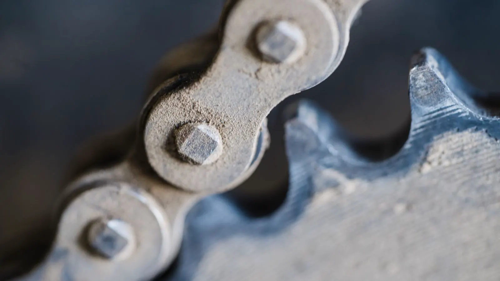
Explainer: How Gear Surface Finish Affects Noise Levels

Gear surface finish noise is driven by microscopic tooth profile deviations. Better finishing reduces vibration and audible sound. Engineers evaluate acoustic performance by checking manufacturing tolerances and selecting finishes that match the application.
- Surface finish quality is the primary driver of acoustic performance in most standard gearboxes.
- Manufacturing tolerances on tooth profiles and runout directly influence the frequency and intensity of generated noise.
- Selecting the correct finishing process, such as grinding or lapping, is often more effective than adding external sound dampeners.
- Engineers should treat noise reduction as a design parameter that must be addressed during the sourcing and specification phase.
Why Surface Texture Matters
Gear surface finish noise is a direct mechanical symptom of how well mating teeth mesh. When two gears rotate, the teeth act as a series of small rollers. If the surface is rough, those rollers catch on microscopic peaks and valleys. This creates vibration.
The vibration transfers through the gear bodies, shafts, and housing. Once it reaches the air, it becomes sound. The lower the surface roughness, the smoother the contact. This reduces the mechanical energy converted into acoustic energy.
For engineers, this link is the starting point for any noise reduction strategy. You cannot fix a noisy drive by simply tightening a housing bolt if the teeth themselves are generating high-frequency vibration. The source is the contact interface.
Consider a high-speed spindle in a machine tool. If the gear teeth have a coarse texture, the meshing contact generates a continuous broadband hum that radiates through the spindle housing. This hum is often the first complaint from operators. It is not the motor. It is not the bearings. It is the friction and impact of the tooth surfaces sliding past one another.
The physical mechanism is simple. As the teeth slide, the high points of the surface roughness strike the low points of the mating tooth. These micro-impacts happen thousands of times per second. Each impact releases a small amount of energy. The sum of these impacts forms the noise floor.
The Physical Link: Asperities and Contact
The term asperity refers to the microscopic high points on a surface that actually make contact when two components touch. Even a smooth gear tooth is rough under a microscope. The height of these asperities determines how the teeth interact.
When asperities are tall or irregular, the contact area is small and concentrated. This creates high local stress. The metal deforms slightly, then springs back. This elastic behavior generates vibration. The frequency of this vibration is related to the speed of the mesh and the spacing of the asperities.
In contrast, a well-finished tooth has asperities that are low and evenly distributed. The contact area increases. The stress is spread over a larger zone. This lowers the peak stress and reduces the energy available to create sound.
Think of the contact area like the tread of a tire on a road. A smooth tire on a flat road produces less noise than a tire with deep, irregular treads on the same road. The same principle applies to gears. The “road” is the mating tooth surface. The “tire” is the rolling tooth surface.
The shape of the asperities matters as much as their height. A sharp asperity concentrates stress and generates higher frequency noise. A rounded asperity distributes stress and generates lower frequency noise. Grinding tends to produce rounded asperities. Machining tends to leave sharp tool marks. These differences show up in the noise spectrum.
The contact mechanics also depend on the material. Harder materials like chrome moly steel hold their shape better under load. Softer materials deform more easily. This deformation can increase the contact area, which reduces peak stress, but it can also increase friction. Friction adds to the noise.
Finishing Processes and Their Impact
The finishing process is the final step in gear manufacturing. It defines the actual surface profile the machine will operate with. Different processes yield different results.
| Finishing Process | Typical Application | Acoustic Effect |
|---|---|---|
| Machining (Honing) | Large, high load gears | Moderate noise reduction; good for heavy loads |
| Grinding | Precision, high speed gears | Significant noise reduction; tightest control |
| Lapping | Final alignment of mating pairs | Best for low noise; corrects residual profile error |
| Shot Peening | Surface hardening | Minimal direct effect on noise; improves fatigue life |
Machining, or honing, is the workhorse for many industrial gearboxes. It is cost-effective and handles large diameters well. However, it leaves a surface profile that is good, but not perfect. It may leave enough microscopic irregularity to generate audible hum at high speeds.
Honing uses abrasive stones or rods to remove material. The process is relatively fast and can be done on large gears. The resulting surface has a characteristic cross-hatch pattern. This pattern is visible under a microscope. At high speeds, the micro-impacts of this pattern create a distinct hum.
Grinding is the next step up. It removes material with abrasive wheels to achieve a very smooth profile. This is standard for high-speed reducers and applications where quiet operation is a design requirement.
Grinding uses diamond or aluminum oxide wheels. The wheels spin at high speeds and remove a thin layer of material. This process allows for tighter control over the tooth profile. The resulting surface is smoother than the one produced by honing. The asperities are lower and more uniform.
Lapping is often a final touch. It uses abrasive pads to bring the mating teeth into perfect mesh. This is expensive and time-consuming. It is reserved for applications where the noise floor must be extremely low, such as medical equipment or high-end robotics.
Lapping involves rubbing the teeth together with an abrasive compound. This process corrects small errors in the tooth profile that remain after grinding. It ensures that the load is distributed evenly across the tooth face. The result is a gear set that meshes with minimal friction and impact.
Shot peening is a different process. It uses small steel balls to bombard the surface. This compresses the surface layer and improves fatigue life. It does not smooth the surface. It does not reduce noise directly. It is used for durability, not acoustics.
How Tolerances Drive Acoustic Performance
Manufacturing tolerances define the acceptable deviation from the ideal tooth shape. These tolerances are not just about the tooth profile. They also cover runout, center distance, and shaft alignment.
A gear can have a perfect surface finish but still be noisy if the runout is high. Runout is the wobble of the gear as it rotates. If the gear wobbles, the tooth profile changes during the mesh. A tooth that was cut to be flat might briefly act like a wedge. This creates a rhythmic impact every time the gear rotates.
This rhythmic impact creates a strong noise signature at the rotational frequency. It is often described as a “thump” or a “whoosh.”
Surface finish noise is usually broadband and high frequency. Runout noise is tonal and lower frequency. A complete acoustic analysis must separate these. If you are buying a gearbox for a quiet environment, you need to check the runout tolerance, not just the surface finish.
Center distance is another critical factor. This is the distance between the centers of the two gears. If this distance is too large or too small, the teeth do not mesh correctly. The load shifts to the edges of the teeth. This creates a different type of impact.
Shaft alignment is also important. If the shafts are not parallel, the teeth engage at an angle. This angle changes during rotation. It creates a varying contact pressure. This variation generates noise.
A practical example is a gearbox in a fan unit. The fan is driven by a motor. If the motor shaft and the fan shaft are not perfectly aligned, the gears experience a cyclic load. This load generates a rhythmic noise that gets worse at higher speeds. Fixing the alignment stops the noise. Polishing the teeth does not.
Sourcing Decisions for Engineers
When selecting a gearbox, the specification sheet is your primary tool. Look for the Ra value, which measures surface roughness. Lower numbers indicate a smoother surface.
However, Ra is only one part of the picture. You must also look at the tooth profile accuracy. A gear can have a low Ra value but a poor profile if the grinding wheel was worn during production. The tooth might be smooth, but it might be the wrong shape.
This is where the concept of “effective” finish comes in. The effective finish is the combination of surface roughness and profile error. A gear with a slightly rougher surface but a perfect profile can be quieter than a gear with a smooth surface but a distorted profile.
Engineers should ask suppliers for test data. If available, request the measured noise level in a controlled environment. This data is more useful than a theoretical calculation. It shows the actual acoustic performance of the unit.
Check the profile error specification. This tells you how much the tooth shape deviates from the ideal involute curve. A high profile error means the tooth is not the right shape. Even if the surface is smooth, the meshing will be poor.
Also check the backlash specification. Backlash is the play between the teeth. Too much backlash allows the teeth to hit each other with a clunk. Too little backlash causes the teeth to bind. Both conditions create noise.
The documentation should include the heat treatment process. The material properties affect the surface hardness. A hard surface resists wear. A soft surface deforms. This deformation changes the contact area and the noise level.
If the application is for a quiet office environment, specify a lower Ra value and a tighter profile tolerance. If the application is for a noisy factory floor, a standard Ra value is sufficient. Do not pay for precision you do not need.
A Worked Example
Consider a parallel shaft reducer driving a conveyor belt. The motor runs at high speed, but the belt moves slowly. The application requires a quiet operation because the belt line is near an office area.
The initial design used a standard honed gear. The surface finish was acceptable for the load, but the noise was too high. The hum was noticeable in the office.
The engineering team reviewed the specifications. They found that the runout tolerance was standard, and the surface finish was standard honing. They decided to change the specification.
They requested a ground gear set with a tighter runout tolerance. They also specified a lapped finish for the mating pair. This increased the cost of the gearbox, but the noise level dropped significantly.
The result was that the hum was gone. The remaining sound was a low-level mechanical whine that was acceptable. The fix was not an external sound box. It was a change in the internal manufacturing process.
The team also checked the shaft alignment. They found a slight misalignment of 0.1 mm. They adjusted the mounting frame to correct this. This adjustment reduced the noise further.
The lesson here is that noise reduction is a system issue. It involves the gear teeth, the shafts, and the housing. You must address each part.
Conclusion
Gear surface finish noise is a function of the mechanical contact between teeth. It is not a random event. It is a predictable outcome of the finishing process and the tolerances applied.
Engineers must treat acoustic performance as a design variable. It starts with the selection of the finishing method. It continues through the verification of manufacturing tolerances. It ends with the validation of the final unit.
Ignoring this link leads to costly retrofits. Adding sound dampeners to a poorly finished gear is like putting a bandage on a broken bone. The fix must be at the source.
By understanding how surface finish drives noise, buyers can make more informed sourcing decisions. They can specify the right level of finishing for their application. They can avoid overpaying for unnecessary precision. They can also avoid underpaying and ending up with a noisy drive.
The choice is clear. For critical applications, invest in better finishing. For standard applications, a well-specified honed gear is sufficient. The key is knowing which category your application falls into.
Frequently asked questions
How do I know if my gearbox noise is from surface finish or alignment?
Surface finish noise is usually broadband and high frequency. Alignment or runout issues create tonal noise that changes with speed. A simple frequency analysis can distinguish between the two.
Is grinding always better for noise reduction?
Grinding reduces noise by improving surface smoothness and profile accuracy. However, it is not always necessary. If the application is low speed and high load, a well-honed gear may be sufficient and more cost-effective.
What is the difference between Ra and profile accuracy?
Ra measures the microscopic roughness of the surface. Profile accuracy measures the macroscopic shape of the tooth. A gear can have low Ra but poor profile accuracy, which will still cause noise.
Can I reduce noise by changing the gear oil?
Gear oil can dampen some vibration, but it cannot fix a noisy gear set. If the teeth are generating high levels of vibration, no amount of oil will make the drive silent.
Should I lapping every gear set?
Lapping is expensive and time-consuming. It should be reserved for applications with strict noise limits. For most industrial drives, grinding is the standard for high-quality finishing.